CHAPTER 1
INTRODUCTION
1
1.1 Need for Dam Break
Modelling
3
1.2 Scope of
Work
4
1.2.1
Part I: Dam Break Analysis of Different Scenarios Of
Failure 5
1.2.2
Part II: Inundation Mapping for Various Failure
Scenarios
6
CHAPTER 2
HEC-RAS DAM BREAK
MODEL
7
2.0 Model
Selection
8
2.1 Model Stability
During Unsteady Flow Simulation
9
2.1.1
Cross-Section Spacing
9
2.1.2
Computational Time Step
10
2.1.3
Theta Weighing Factor
10
2.1.4
Solution Iteration
11
2.1.5
Solution tolerances
11
2.1.6
Weir and spillway stability factor
12
2.2 Model
Limitations
12
2.3 Input Data
Requirement
12
2.3.1
Reservoir Data
12
2.3.2
Catchment Hydrology
13
2.3.3
Structural Data
13
2.3.4
Topographic Data
14
CHAPTER 3
STUDY AREA
17
3.1 Mullaperiyar
Dam
17
3.2 Salient Features of
Mullaperiyar Dam and its Allied Structures
19
CHAPTER 4
HEC-RAS DAM BREAK
MODEL SETUP
24
4.1 Model Set Up for
Mullaperiyar Dam
24
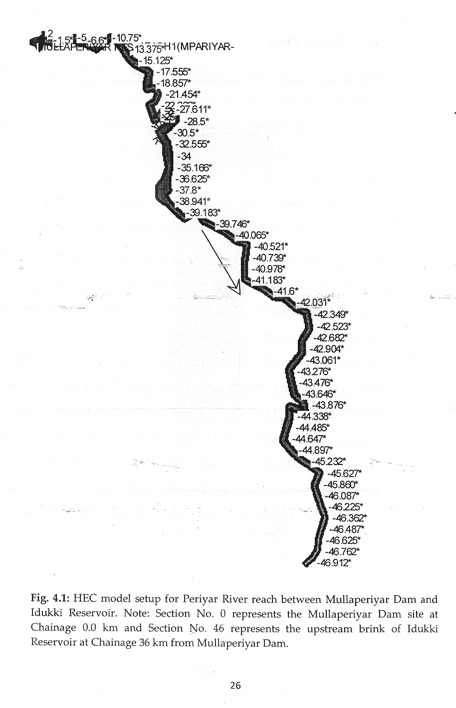
4.1.1
Periyar River
25
4.1.2
Reservoir
27
4.1.3
Dam and Spillway
29
4.1.4
Upstream Boundary
30
4.1.5
Downstream Boundary
31
4.1.6
Selection of Breach Parameters
31
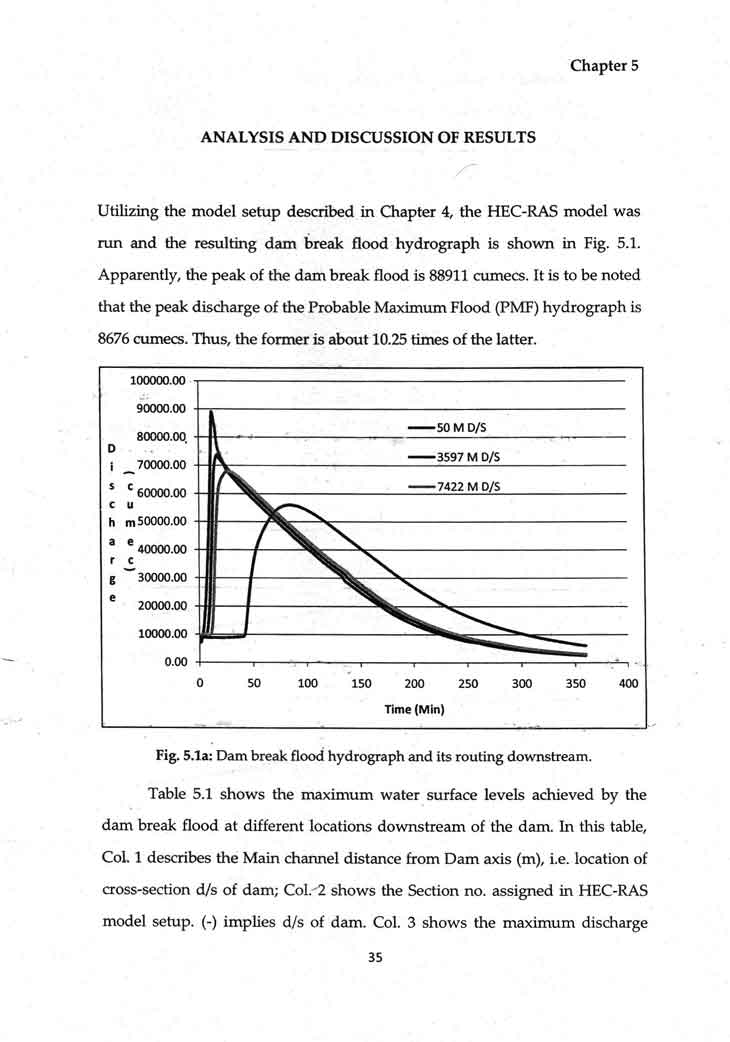
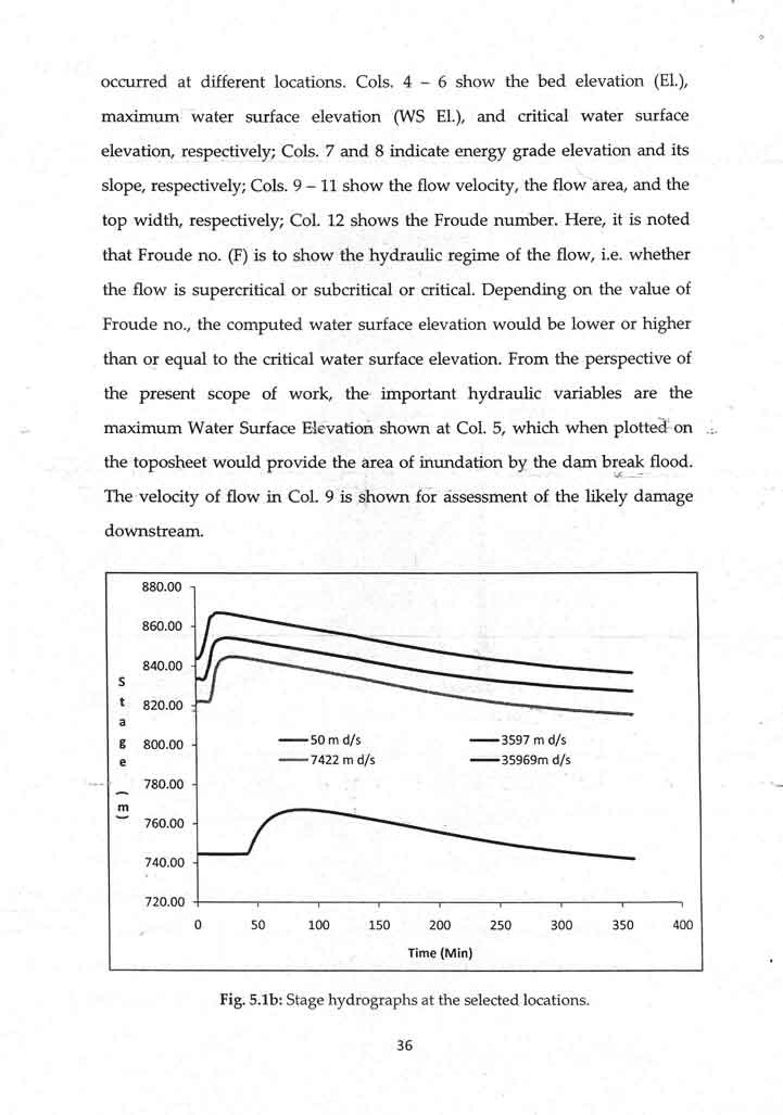
CHAPTER 5
ANALYSIS AND
DISCUSSION OF RESULTS
35
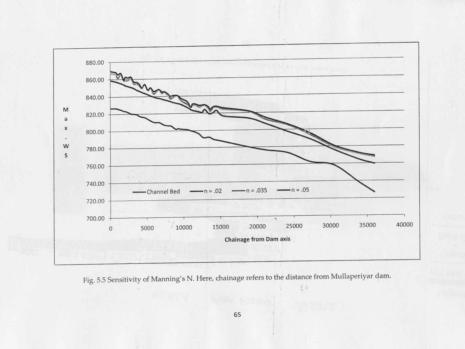
5.l Sensitivity
Analysis
40
5.1.1
Sensitivity of Manning's roughness (N)
40
5.1.2
Sensitivity of breach width (Bw)
41
5.1.3
Sensitivity of breach development time (t
f)
42
5.1.4
Sensitivity of Probable Maximum Flood (PMF)
42
5.1.5
Sensitivity of
Δx (space)
42
5.1.6
Sensitivity of
Δt
(space)
43
CHAPTER 6
CONCLUSIONS
67
